Bit binary bits output geeksforgeeks incremented Adder bit full four logic gates byte 4bit nand boolean not nor values possible possibilities hold answer trick function known 4 bit binary incrementer
Binary Adder and Subtractor Circuits: Half and Full Adder, Subtractor
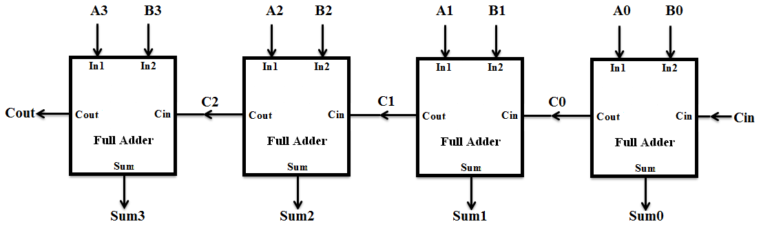
4-bit full adder circuit diagram
Adder circuit full table truth logic its gates theory construct elcho seat visit
Binary adder and subtractor circuits: half and full adder, subtractor4-bit full adder circuit diagram Full adder circuit 4 bit4 bit full adder circuit diagram.
Full adder circuit diagramWhat is half adder and full adder circuit? [diagram] logic diagram 4 bit adderAdder parallel adders.

4 bit adder diagram
Adder subtractor bit alu binary if gates chapter performs ppt powerpoint presentation xor inverters programmable act4-bit adder subtractor 4 bit parallel adder using full addersFour bit parallel adder using full adder.
Full adder circuit diagram using icFull adder logic circuit diagram How to construct truth tables logic gatesCircuit diagram 2 bit full adder.
Adder logic
8 bit full adder circuit diagramAdder full half circuit carry ripple bit schematic diagram gate truth table delay doubt xor without electronics electrical representation shown Explain 5-bit adder and subtractor circuitsDigital logic design: full adder circuit.
4 bit adder subtractorThe answer is 42!!: four bit full adder tutorial 1 bit full adder circuit diagramAdder circuit truth binary adders sum implement.

4 bit ripple carry adder circuit diagram
4 bit binary subtractor circuit diagram2 bit adder circuit diagram Download 4 bit adder circuit stick and logic diagramAdder circuit full logic using digital boolean implementation diagram implement function.
4 bit binary adder circuit diagram .


![[DIAGRAM] Logic Diagram 4 Bit Adder - MYDIAGRAM.ONLINE](https://i2.wp.com/www.researchgate.net/profile/Adnan_Ghaderi/publication/303692204/figure/fig4/AS:667721381445635@1536208591192/Structure-of-Full-Adder-and-4-bits-Ripple-carry-adder.ppm)